As we saw in part 1 their output is a very simple function of their inputs describable with a very simple truth table.
Design a combinational circuit that generates output as 1 only for particular input pattern.
The previous state of input does not have any effect on the present state of the circuit.
A device with n binary inputs and 2 n binary outputs.
It uses a decoder circuit to perform this selection.
Compare two 1 bit numbers.
A decoder can be thought of as converting an n bit input to a 2 n output.
This is time independent.
The combinational circuit do not use any memory.
Multiplexer is a combinational logic circuit which allows only one input at a particular time to generate the output.
The signals which control which input will be reflected at the output end is determined by the select input lines.
These functions can be described using logic expressions but is most often at least initially using truth tables.
A multiplexer is often written as mux in the abbreviated form.
The output of combinational circuit at any instant of time depends only on the levels present at input terminals.
Terms the each output is a function of the inputs.
The control unit must select the correct two registers based on these two 4 bit patterns in the instruction.
In even parity bit scheme the parity bit is 0 if there are even number of 1s in the data stream and the parity bit is 1 if there.
There is no feedback between input and output.
Given two input bits a and b produce three outputs x y and z so that x is 1 only when only when a b y is 1 only when a b and z is 1 only when a b learn more.
Each bit pattern at the input causes exactly one of the 2 n to equal 1.
Repeated numbers should consider as single number design a combinational circuit that generates.
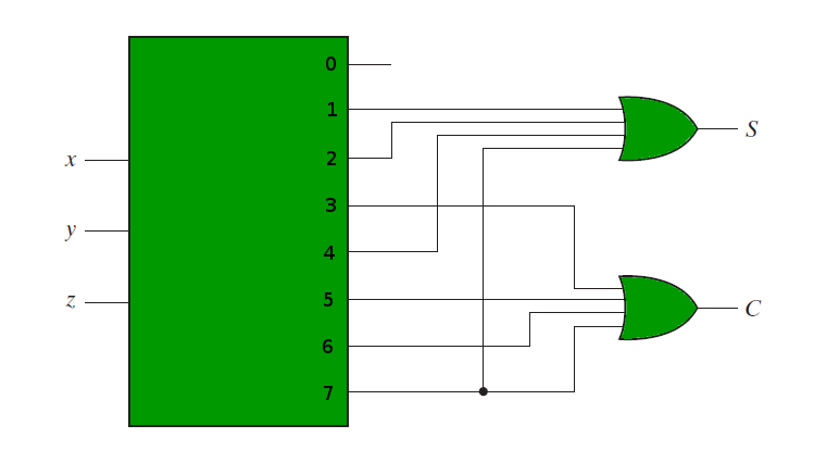
Draw the logic diagram using the and or gates and discuss its inference.
For each possible input combination there is one and only one possible output combination a combinational circuit can be describe by m boolean functions one.
Draw the truth table for a combinational circuit that generates output as 1 only for particular input pattern double the student s vtu number 14974 write the boolean expression in standard sop form design nand nand implementation nor nor implementation for that expression derived from i design a data selector circuit for that truth.
Design a circuit that has a 3 bit binary input and a single output that output 1 if it is a prime number.
It is designed easy.
This additional or extra bit is termed as a parity bit.
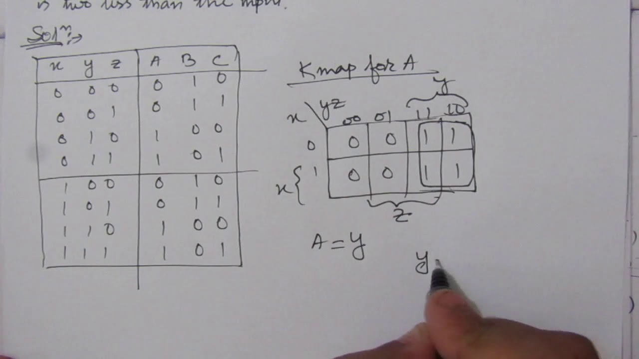
Questions marks 1 4m design a combinational circuit that generates output as 1 only for particular input pattern student s vtu number use k map for boolean minimization.
Combinational circuit in this output depends only upon present input.
Sequential circuits are those which are dependent on clock cycles and depends on present as well as past inputs to generate any output.
A combinational circuit can have an n number of inputs and m number of outputs.
Eg 2 10 3 10 5 10 7 10.
A combinational circuit consists of input variables n logic gates and output variables m.